Nuclear power has long been a clean dependable source of energy throughout the world. However, as power plants age, concerns grow on their continued reliability. There are many components that make up the infrastructure of a nuclear power plant with the design intent to reduce radiation and contamination exposure to personnel, equipment and the surrounding environment.
One of the biggest sources of this radiation and contamination comes from the vast network of pipes throughout the plant.
In a Pressurized Water Reactor (PWR), the primary coolant (water) is a closed system of pipes and other components that pumps radioactive water and steam under high pressure to the reactor core where it is heated by the energy released by the fission of atoms. The heated water then flows through the pipes to a steam generator, thermal energy transfers to a secondary system where steam is generated and flows to turbines which, in turn, spin electric generators.
If there is a failure anywhere in the pipe system, it could be disastrous. The Nuclear Regulatory Committee was concerned that these critical pipe systems are experiencing wear from corrosive agents which could result in a leak and jeopardize the function of the plant, while subjecting the critical mechanics and personnel to a dangerous and unexpected situation.
Since the corrosion in question is occurring on the inside of a pipe, it is obviously an unseen problem to a visual inspection. One of the sources of corrosion comes from gases that can get trapped in a pipe. In following the basic laws of physics, gas will rise to the highest points of any system. Inside a pipe, an unintended high point can become a resting position and a potential catalyst for a catastrophic corrosive breakdown to occur.
The concern was so much of a significance that a PWR plant in Kansas wanted to assess the issue with the measurement of several of its pipe runs. The solution was to install vents once the high points were identified to alleviate any gas trapped since it was easier than replacing the entire pipe stretch. As simple as this sounds, the effort was not without tremendous risks since many of the systems were difficult to access and emitted high levels of radiation. At the time, the only known way to measure these systems was with manual hand tools. The involved process would result in many personnel being exposed to high levels of radiation, potential contamination and other unsafe processes using ladders and scaffolding.
Hand measuring can be an effective tool for dimensional inspection, but in this case it was not sufficient. Any highpoint, as small as it may be, is still a place where gases could collect and corrode. Typical conventional surveying with a tape measure, ladders and scaffolding was determined to be an undesirable method for this facility. The inaccuracy and potential for human errors with hand measurements could very well result in subtle rises in pipe being missed. The contractor tasked with the project responsibilities immediately recognized this risk and directed their client to the professionals at Exact Metrology for assistance.

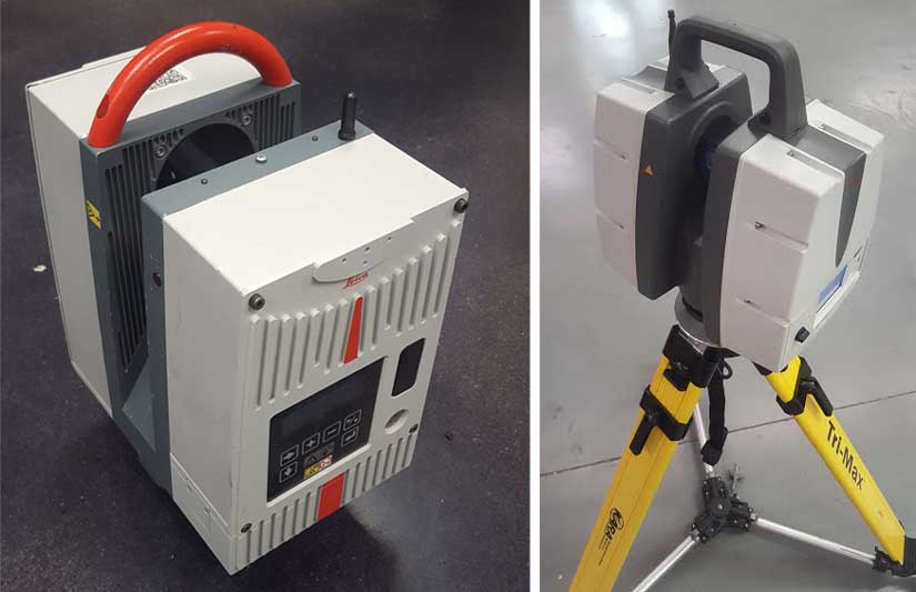
Left: Actual Scanner Used on Job, Right: Updated Scanner
After conferring with project management, reviewing the site conditions, and understanding the critical elements of the project, four metrology professionals from Exact Metrology were deployed to the facility.
While donned in full radiation protection suits, Exact Metrology personnel scanned piping in over two dozen rooms throughout the power plant utilizing Leica HDS scanners. The Leica scanners were capable of capturing full-volume, 360-degree 3D point clouds in about three minutes. Some rooms only required a single setup, which resulted in minimal exposure times to the harsh nuclear environment. Once a scan is initiated, the data acquisition is completely automated allowing the Metrologist to retreat to low dose areas while critical data continues to be captured by the device. Once scanning was completed, the multiple scan setups were stitched together to form one large point cloud. This allowed the users to extract data from any section of the pipe run and from any perspective. Complex software algorithms then provided a function to extract all pipe sizes, centerline and position even when only part of the pipes were scanned. As an added benefit, the dense point cloud obtained was able to reveal areas of crystallization, which indicated that leaks in the pipes were already in progress.
The advantages of using 3D scanning versus the traditional “tape measure and ladder” of the past, were numerous. The elimination of human error, greater accuracy and speed were the obvious upsides. Operator safety, especially in high radiation/contamination areas, was greatly increased due to the speed and operational characteristics of the scanners which allowed operators to spend minimal time in dangerous rooms. The scanners allowed the operators to take measurements from the ground, avoiding the danger associated with ladders, scaffolding and harnesses. Scan from ground level also avoided needing permits which would have been required to climb ladders above a certain level, fall protection, air monitoring in higher elevations and contact with possible contaminated surfaces above.
Another advantage of 3D imaging over other methods is that it allows for additional measurements to be taken after-the-fact. With standard measuring, once you’ve left a site, if a measurement was missed or additional measurements are required, a revisit is required to re-measure. If the plant is up and running again, re-entry will be denied. However, with 3D scanning, the data is picture quality, and by looking at the file from a computer, you can revisit all of the details that were captured at any time. If it’s determined that additional measurements are required, it’s as easy as re-visiting the virtual point cloud on your computer and extracting the required data. No need for an additional site visit!
Once scanning was completed, 3D CAD models were generated and computer snapshots were recorded with elevation descriptors marked on each side of the pipe runs. The report showed a graphical description of the model pipes with the elevation provided in a PDF form. These reports were sent to the facility engineers to determine if there was a need to install vents at specific locations on the pipe runs. According to Greg Hoeting, Applications Engineer and onsite Project Manager from Exact Metrology, test results were found to be acceptable by the facility engineers and they were able to take action to correct the problem. Due to the proprietary nature of the nuclear power plant facility, no further results were made available.
Probably those that might have been happier about the project were the folks in health physics. The dose levels that the crew received were substantially lower than ALARA goals set at the beginning of the task.
*ALARA – As defined in Title 10, Section 20.1003, of the Code of Federal Regulations (10 CFR 20.1003), ALARA is an acronym for "as low as (is) reasonably achievable," which means making every reasonable effort to maintain exposures to ionizing radiation as far below the dose limits as practical, consistent with the purpose for which the licensed activity is undertaken, taking into account the state of technology, the economics of improvements in relation to state of technology, the economics of improvements in relation to benefits to the public health and safety, and other societal and socioeconomic considerations, and in relation to utilization of nuclear energy and licensed materials in the public interest. U.S. NR – United States Nuclear Regulatory Commission


